|
Marker Trouble? Read Maintenance Archive |
Post Reply 
|
Page 12> |
| Author | |
KRL15 
Platinum Member 
Afghanistan Five-Oh Joined: 24 December 2002 Location: Haiti Status: Offline Points: 6816 |
 Post Options Post Options
") Thanks(0) Thanks(0)
 Quote Reply Quote Reply
 Topic: Marker Trouble? Read Maintenance Archive Topic: Marker Trouble? Read Maintenance ArchivePosted: 03 November 2003 at 1:57pm |
|
"theguy", "Enos", "Rambino", "Hell's Oracle" and others have written some very good Tech articles. This new Thread is for those folks, and others, to Copy and Paste their old articles into. When someone writes a new article, that new article can be "Stickied" as a Stand Alone Thread for a couple of weeks or so, in whatever Forum that you think is the best place for it to be initially Posted. After the New Stand Alone Thread has run its course, Copy and Paste it into this Uber Thread. When that is accomplished, UN-Pin your old Thread. Another option would be to Post a new article as a Stand Alone Thread AND put it here. Then, in a couple of weeks, un-pin the Stand Alone... Whatever.. If it makes good sense, just do it. Use your 'Unlimited Edit Buttons" to update and maintain your own articles. When you use "Clear Form", your Post location in a Thread remains the same. You can then reinsert new material into the old Post that you "Cleared". The Thread for Parts Diagrams will remain as a Stand Alone Thread for such diagrams, manuals, etc. ENOS will manage that Thread. Some of the Posts in that Thread, blow out the Thread really wide on Standard Res Monitors. Also, some of those Posts require Image Hosts, which can change or be deactivated. So, keep the Diagrams and Manuals in THAT Thread, NOT in this Thread. EDIT: Here is an Oldie but Goodie... This is a Link that SL-68 Owners may find useful, by Dan Main Man: Edited by KRL15 |
|
|
That which does not kill you often makes you stronger.
|
|
 |
|
|
Rambino
Platinum Member

I am even less fun in person Joined: 15 August 2002 Location: United States Status: Offline Points: 16593 |
Post Options
Thanks(0)
Quote Reply
Posted: 03 November 2003 at 2:50pm |
|
FAQ: Cyclone Feeder Problems A relatively common post in this forum is the "my Cyclone isn't feeding," or "my Cyclone is breaking balls." Usually these are actually the same problem. Most Cyclone breaks are from partial or slow turning. Hopefully this thread can be a collection of suggested checks and fixes. I'll start. The following is mostly a collection of things I have read, and certainly not all my own wisdom. First: Option B, with any Tippmann gun, is to send it to Tippmann for repairs. They WILL fix your gun, and their interpretation of their own warranty is so liberal that they almost certainly won't charge for labor, no matter how old your gun is, and won't charge for parts either for newer guns. But since it takes some time for the gun to go from here to there and back - time for you without your gun - you should try the hints below first. Parts references are to the A-5 parts chart. General Trouble-Shooting: Whenever you have a problem (of any kind), you should first try some basic de-bugging to isolate the source of the problem. Try some different paintballs. Try a different tank. Take off your upgrades and try the gun stock. Mix and match different elements, and before you know it, you will know exactly where the problem lies. Air Supply: Most Cyclone problems, in my experience, are really an air supply problem. The Cyclone needs a fair amount of air to work, and if it gets starved it won't be happy. The Cyclone is usually the first thing to go, so your gun might be working just fine otherwise, but your Cyclone will skip if it doesn't get enough air. - Tank. Make sure your tank is full. If you have HPA, make sure the tank has output pressure of at least 750 psi. Make sure the tank valve is fully functional and not obstructed. - Drive spring/RVA/Stock. If your drive spring is weak, not enough air will get to the gun, and the Cyclone will be starved. Try a different drive spring. If you have a rear velocity adjuster or a stock, or anything else that replaces the endcap, take it off. Some of these don't put enough pressure on the drive spring, which gives the same result as a weak drive spring. - Regulators: If you have a regulator, make sure you don't have the pressure turned down too low. As with all air problems, your gun might fire fine, and your Cyclone might even keep up, to a point, but insufficient pressure will cause problems. Also remember that the perfect regulator setting for one tank might be too low for another tank, or too low for that same tank when it isn't full. - On/Offs. Some drop-forwards or ASAs with on/off valves can leak or obstruct air flow if they are opened too much. Dirt and crud can also get caught in on/offs. Make sure the valves are clean. When opening the valves, only open until you reach full pressure, and then another full turn. - Remotes: There are many places a remote might have a small obstruction or leak. Check each connector, and your slide check if you have one. - ASA Pins: Some regulators/x-chambers/remotes/adapters push too far into the ASA so that the ASA pin strangles the air. Some ASAs on the tank end of remotes create the same problem. If this is the case, an extra o-ring stuck into the ASA (or remote adapter) will create the extra space needed. - Leaks: Check hoses, connectors, o-rings. Remember, a small leak might let your gun shoot but still impede the Cyclone. Make sure to check the cup seal 02-63) on the piston (02-54) inside the Cyclone manual advancer. Make sure all o-rings are well oiled. Friction: The Cyclone needs to be able to turn freely. Make sure your gun is well oiled. Oil in the ASA will make its way into the Cyclone and help it along, but some oil directly in the manual advancer won't hurt either. A little lithium grease under the ratchet (19, 02-53) might also help if the ratchet is not moving smoothly. Make sure that the feeder screw (8, PL-42A) is not tightened so hard that it keeps the ratchet from turning. This screw should be tightened just enough to keep the sprockets in place. To see if you have friction problems, try the manual advancer slowly. There should be some clicks and different degrees of resistance, but the Cyclone should still turn smoothly, and there should be no "hangs" - the Cyclone should keep up with the manual plunger. Updates: Two updates have been issued for the Cyclone. Both are available free from Tippmann - just call and ask. To check for the first one, take off the bottom plate of your Cyclone (02-44). If the ratchet is black plastic, you do NOT have this update. The updated ratchet is clear plastic. To check for the second update, take a look at the bottom plate itself. The second update is a new bottom plate, and the new bottom plates have an "A" stamped on the outside. Pretty hard to miss. No "A", no update. The first update was intended to stop initial problems with Cyclone breaks resulting from the Cyclone hitting the balls too hard - hence the softer clear ratchet. The second update was intended to keep the first update from backfiring, by stopping "overtravel" of the piston, which the first update parts might allow, which leads to breaks. Tippmann also offers an optional flow control (like the RT flow control), for $15. Not usually required, it may give additional assurance when using brittle paint, by allowing you to limit the amount of air to the Cyclone. Worn Ratchet: A common problem, mostly for people with the first update but not the second, but not impossible in other situations. If your Cyclone starts increasingly skipping shots (and you are shooting blanks), you might have this problem. It might turn normally with an empty hopper, and the manual advancer will work, but fully loaded it will skip and/or chop. The problem here is that the softer clear ratchet is, well, softer, and therefore more prone to wear and tear. Take a close look at the ratchet. The edge that catches the feeder axle (20, 02-49) should be crisp. If the edge is rounded, worn or torn, you have this problem, and you need a new ratchet. Call Tippmann. Try holding the sprockets in place while pushing the manual advancer. The ratchet should hang on the feeder axle. If the ratchet slips off, you have this problem. I actually carry extra ratchets to guard against this problem. Ratchet Spring: Another recent problem is the spring that holds pressure against the ratchet and keeps it from turning back (11, 02-50), has rusted through, or somehow gotten bent out of shape. The obvious way to look for this is to pull the bottom plate off and look to see for a broken or wrongly bent spring (the spring should have a slight bend). Sympoms are similar to a broken ratchet, except with this one the Cyclone will be able to turn backwards. Poor Paint: The Cyclone requires good paint, as it does manhandle the paint a bit. Don't use Wal-Mart paint, don't use old paint, don't use brittle tournament paint. Other Sources: Of breaks, that is. Clean your Cyclone. Crud in the Cyclone will cause breaks. And make sure that the break is actually in the Cyclone. A breech break or barrel break might splatter back into the Cyclone, making it look like you had a Cyclone break (and the splatter might actually cause Cyclone breaks). And check for other obstructions in the breech that could stop a ball from fully entering the chamber. Some barrel adapters, for instance, extend too far back into the breech, and can cause breaks in this manner. Edited by Rambino |
|
|
[IMG]http://i38.tinypic.com/aag8s8.jpg">
|
|
|
|
|
theguy
Platinum Member

Guested, F-Bombs In Posts Joined: 05 October 2002 Location: Antarctica Status: Offline Points: 5308 |
Post Options
Thanks(0)
Quote Reply
Posted: 03 November 2003 at 4:06pm |
|
Class1 why the flatline seems innaccurate
Why the Flatline SEEMS Inaccurate. Lets start with our diagram. A is our shooter. Now, no barrel is dead on accurate. They all have a margin of error. Lets say that the margin of error in this picture is about 5 degrees. Shooting a standard barrel (B), it seems very accurate at its maximum range. However when shooting a flatline (C) which has the same margin of error as a standard barrel, it spreads over a larger area but actually is just as accurate as barrel B. So hopefully now you will understand why you are getting great range form your flatline, but not hitting dead-on. Edited by theguy |
|
|
|
|
|
|
|
theguy
Platinum Member
Guested, F-Bombs In Posts Joined: 05 October 2002 Location: Antarctica Status: Offline Points: 5308 |
Post Options
Thanks(0)
Quote Reply
Posted: 03 November 2003 at 4:07pm |
|
Class3 how to polish your internals (class2 was lost in the forum change)
Welcome to yet another class by Theguy. This time we are going over how to polish your internals. Please note your availability to tools may not be as abundant as mine, so you may have to improvise. Lets start out shall we. Start off by taking apart the halves of your receiver. This is for the 98 and A-5, closed body receivers are much more difficult. Take apart the body halves and clean them up the best you can.
Note- my internals are already polished, pretend they arn't. I used the plastic brush attachments on my Dremel to clean everything up. The Dremel can also be used as an alternative to a bench grinder.
Now set yourself up a err umm........ clean workspace.
I chose to use the benchgrinder for this demonstration, its size makes it easier to photograph, and I don't have to hold it, freeing up my camera hand. Apply a polishing compound to your polishing cloth/wheel
Take your body and press it to the wheel gently at first then rougher later. Make large sweeping strokes with the body, making sure to polish everything evenly. Tilt the body both away and toward you to get the tops and bottom.
Reapply some compound and do the other half. In my process there are 2 different grades of compound. Apply your second grade and repeat the process. Then get a clean rag and wipe away any residue. Don't worry if your wheel/cloth turns black, this is from the Nickel coming out of the aluminum. Wipe everything clean and reassmble. Only polish until the sides are smooth and shiny, if you keep going you could remove too much metal.
The benefits of polishing should be apparent when you firt gas it up. By creating a smooth surface for the bolt to slide across, you reduse the friction and your air efficiency goes up. When I polished my internals my velocity shot up about 150 fps, I had to screw in my velocity screw all the way in , just to shoot 280. With adjustments from an RVA or a reg, you could get more shots out of your tank and run at amuch lower pressure. |
|
|
|
|
|
|
|
Enos Shenk
Platinum Member

~-o@ Joined: 10 June 2002 Location: A comfy chair Status: Offline Points: 14109 |
Post Options
Thanks(0)
Quote Reply
Posted: 03 November 2003 at 6:01pm |
|
So i guess were archiving the class posts here too? Ok. Heres 4.
Class 4: The Wonderful World of Trigger Jobs By Enos Shenk To quote the Autococker dude Ravi, "The trigger is the most important part of any paintball gun," If the trigger feels like crap, and is sloppy, or takes a mile to pull, you wont have as much fun with the gun. Doing some basic work on your trigger can make your gun cycle faster, feel snappier and more responsive, and be rewarding to know that you did it yourself. This might seem way over the top, but your trigger is honestly the most important and personal part of your gun. If you dont like the way it feels or the way it shoots, your not going to be happy with any of the gun. Most of these mods are easily accomplished with basic hand tools, and items found around the house, however a Dremel Tool is something no gun modifier should ever be without. A dremel will help you in so many ways you cant even realize until you use one. Im going to go over the workings of the trigger mechanism itself, feel free to skip this part for now if its seems long, but come back to it later as a reference if you want to attempt a trigger mod yourself. It will help! Now first of all, you need to understand the basic functions of the trigger assembly in a Tippmann. The 2 main parts are (obviously) the Trigger, and the Sear. The Sear's job is to catch and restrain the rear bolt, and the triggers job is to pivot the Sear to release the rear bolt to fire the gun. The Sear has 1 oval hole in it for a very important reason. When the gun is "At rest", that is, not cocked, the Sear is held about 1mm away from the trigger. When the gun is cocked, the Drive Spring is attempting to push the Rear Bolt forward, since it is held by the Sear, the Sear is also pushed forward so it meshes with the trigger. This is what makes your gun Semi-Auto, and on a real firearm is known as the Disconnector. The actual piece that the sear rests on is known as the Trigger Slider, its a U-Shaped piece of metal that slides over and around the back of the trigger, is held in with 1 pin, and is forced out with a spring. If you fire your gun, and hold the trigger in after the shot, you will feel the rear bolt "pushing" on the trigger, because the force is translated along the rear bolt to the sear and to the trigger slider. When you let off, you will feel a small click as the sear slides above the trigger slider, and the gun is ready to shoot again. Heres a handy drawing of the trigger assembly with the parts labeled for you.  The trigger assembly in full consists of the Trigger (#1), the Sear (#2), the Trigger Spring (#3), the Sear spring (#4), the Trigger Slider (#5), and the Trigger Slider Spring (#6). Almost all of these parts can be adjusted and tweaked in many ways to make your trigger feel exactly how you want it. Now, an important part. Remember this, write it down, tattoo it onto your hand. This is the GOLDEN RULE OF TRIGGER MODDING: THOU SHALT NOT ADJUST THE SEAR SPRING! Messing with the sear spring generally will just throw your gun out of whack, cause it to shoot "full auto" or not recock, and generally give you a big fat headache. YOU HAVE BEEN WARNED! The most basic mod, the "Pen Spring Mod". This is absolutely the easiest and cheapest mod to accomplish. Simply removing the Trigger Spring (Part #3 in my picture) and replacing it with a spring of roughly the same size and length, but a lighter weight, will lower the amount of force you have to pull the trigger. Do not completely remove the spring! It can and will cause the sear to "Jam" on the back of the Trigger Slider, not something you want to happen in a heated match. The pen Spring Mod is a good place to start, and will serve as a basis for more advanced mods. The second easiest mod, and the most overlooked trigger mod ever, is the Trigger Slider Spring Mod. This spring is Part #6 in my diagram (Inside the slider). This is the exact opposite of the Pen Spring, as you will be STRENGTHENING this spring. If you read above what i told you about the way the disconnector works, you know that the only time the Trigger Slider Spring is used is after the gun has fired, right as the gun cocks and latches, and your finger is more then likely still on the trigger (Because the gun cycles so fast). By replacing this spring with a stronger one, your trigger will gain noticably more "Snap" or "Bounce". Its almost comparable to a Mini-RT, but dont expect anything near as strong as an RT, but its the same feeling. I LOVE this mod, as trigger snap is one of my favorite properties in a trigger. Moving up in difficulty is the Trigger Side-To-Side Slop fix. Side-to-side slop is where you can "waggle" the trigger sideways. Its not desirable at all, and generally makes your trigger mushy and sloppy. But it is fairly easy to remove, most especially on a carbine or a 98. Simply visit your local hardware store and find some small steel washers that will fit over the Trigger pivot pin. Give them a bit of oil and drop them in. If they seem too thick, just use 1 on one side. If you can fit, go for 2. A carbine will easily accomidate 1 washer on each side. Obviously you want the trigger to still move smoothly. Now we can start getting complex, and somewhat gun-specific. Overtravel and Rest Distance are 2 adjustable values that can be somewhat difficult but fun to fix. Overtavel refers to the distance that you have to pull the trigger before it engages the sear, and fires the gun. Rest Distance is my term for how close the trigger is to the firing point "at rest" as in, when its not being pulled, and is just sitting there. Common methods for Overtravel Adjustments: Wrapping tape or otherwise thickening the gun safety (Carbine only) Adding a piece of Q-Tip stick or a Grub Screw into the middle of the Trigger Spring (98c and A5 Only) (A grub screw is a bolt with no head. The same sort of screw used for velocity screws on a 98 or an A5) Adding a Grub Screw or a bolt to the trigger itself, so it hits the grip behind the trigger at the firing point. Adding a Grub Screw or a bolt into the grip behind the trigger, does the same as the above. Common methods for Rest Distance adjustment: Gluing a piece of CD-Case plastic onto the top of the A5 Trigger, so it rests against the reciever above, effectively bringing the trigger back a bit to start with. Ive heard this only works well with the E-Grip. Wrapping tape or something else around the pin that the trigger-end of the sear rests on in a 98. This will make it so the trigger doesnt have to move as far to release the bolt. Obviously this one is useless without a means of also keeping the trigger back at rest like the CD-Case mod above. Its interesting to note that theres no reason you couldnt even lengthen the pull on a 98 or an A5 if that was your choice. By sanding off some of the plastic along the top of the trigger, it would sit farther out, adding some distance to the pull. But its all up to the user. You can use any or all or none of these mods for your gun to get your trigger exactly how you like it. Use your ingenuity, use your imagination, and dont be afraid to try things for yourself. If you mess up, more then likely you just screwed up the trigger, which is maybe a $2 part from Tippmann. So go hog-wild, and be sure to post any cool trigger jobs in Upgrades & Customizing for other people to ooh and ahh over. In case your wondering, my preferred trigger is a bit on the long side, medium weight pull, no slop at all, and lots of snap  Hope it helps |
|

|
|
|
|
|
EYES
Platinum Member

More pansy and liberal and commie than U Joined: 07 October 2003 Location: United States Status: Offline Points: 3588 |
Post Options
Thanks(0)
Quote Reply
Posted: 10 November 2003 at 5:01pm |
|
Barrel Problems??? Side note: Sometimes the threads on the 98 and the barrels don't completely match up perfectly, causing some mis-alignment. *NOTE* I have also found it helpfull if you have a metal front grip or a vertical adapter. It prevents you from over-tightening the front grip screw. Edited by EYES |
|

|
|
|
|
|
*(New) Fnd Glry
Member 
Joined: 13 August 2003 Location: United States Status: Offline Points: 390 |
Post Options
Thanks(0)
Quote Reply
Posted: 26 November 2003 at 2:59pm |
|
Making Your Own Grips - Class 6B
In this article, I will cover how to make the grips, as seen in the pictures below. I made these myself, as some of you may know. I've always wanted to post an article about this, but I kept putting it off. But now, Ive put off all the procrastination, and have decided to finally just sit down and do the thing. So, all you die-hard customizers and future fabricators out there, this is the article for you. Note - You will need access to metal shop equipment in order to accomplish this.  First, note the picture above. This is my reference for the rest of this article. In case you cant read that, the top measurement is 1-¼ inches, the right measurement is 4 inches, the left measurement is 3-7/8 inches, and the bottom is 1-½ inches. For this project, you will need two small pieces of diamond plating (type of metal is unimportant for this particular project). The size must be larger than the parameters I have specified in the drawing. You will need a sheer (maximum cutting thickness must be at least the thickness of the metal), and you will also need a drill press (a hand-held drill may come in handy for the latter part of the project), and you will need a bench grinder, as well as a buffing wheel (to make it look purdy after youre finished with it  ) ) Well, now to get started First, make a to-scale version of the grips out of poster board. Make sure it fits on your gun just the way you want it. Make sure to make holes in the paper exactly where you want your holes to go on your actual grips when it comes time for it. Note These plans I have posted are for a .45 grip frame. They should fit all Tippmanns, but you should check to make sure before you cut the metal. Use the poster-board to draw an outline on your material. (be sure to flip the paper over when you draw the opposite side, otherwise you could end up with two grips of the same side. Also, make sure that the diamond is facing out.) Use the sheer to cut the metal close to the lines, but be sure not to cut ON the line--keep it about 1/16 of an inch away from the line (on the outside edge, of course). Use the bench grinder to grind down the extra 1/16 of an inch or so, as well as grind in the corners to a smooth curve. Also, bevel the outside edge of the metal. Next it is best to drill the holes. You will need to be very precise in placing your holes. The width of the holes can be estimated by gauging them from the last set of grips on your marker. Im not 100% positive, but I believe the hole is around 1/8 of an inch. Next, take some sandpaper, and begin sanding the edges you beveled until it is as smooth as the face of the grips. This usually takes quite awhile, but is necessary for a smooth and high-quality piece of work. After you have sanded all of the bumps out, buff it with the buffing wheel. I used a buffing brick with the wheel, and after about 15 minutes, I had the look I was looking for. Next, attach your grips to your gun, and make sure you have the look and feel youre looking for. If anything is wrong, fix it as you see fit. The finished product should look as such, or similar:  Now, if youre interested in more information from me, feel free to PM me. Id be glad to help you out. Good luck with the project! <Nice!><KRL>
Edited by KRL15 |
|
|
Pimpin' since May 26th, 1987
|
|
|
|
|
Rock Slide
Platinum Member

Well, my player card says Im an <KRL> ! Joined: 10 June 2002 Location: Botswana Status: Offline Points: 6612 |
Post Options
Thanks(0)
Quote Reply
Posted: 31 December 2003 at 8:26am |
|
Timing the Tippmann F/A
6-M. Rate of Fire Adjustment FULL Automatic To adjust rate of fire make adjustment to the brass rate of fire adjuster screws located in the sight portion of the cover/sight/shock-sear assembly on the upper receiver. · Unload ammo and remove constant air as on page 4 · Unscrew the rear sight cover locking jam screw and then the inner jam screw. · Slide the cover forward to reveal the brass rate of fire adjuster screws in the front end of the cover/sight/shock-sears assembly. NOTE: DO NOT air-up and fire gun with this cover removed. This cover holds the linkage arm in place and personal injury or damage to the gun could result. To Adjust Firing RateFine-tune the rate of fire with small adjustments to the brass needle valve rate of fire adjuster screw. This screw is the one on the left when looking at the gun from the front. · IN (clockwise) to slow down. · OUT (counter clockwise) to speed up. NOTE: If you make a big adjustment (a full turn is a big adjustment) then the right oil adjuster screw also needs to be readjusted to maintain proper spacing in the shock cylinder. To Adjust ShockThe Shock Adjuster Screw is the one on the right when looking at the gun from the front. Shock cylinder adjuster screw needs adjustment approximately every 2000 rounds (1-case) or when a major rate of fire adjustment is made to the other Rate of Fire screw. · Turn the brass shock cylinder oil adjuster screw all the way in (clockwise). This should prevent the shock sear from fully releasing. · Next pull the bolt handle back and then release the bolt handle, it should stop before it gets to the normal ready to fire position (and trigger should not work). If the bolt doesn't get stopped before it gets to the normal ready to fire position the shock cylinder needs oil added and possibly rebuilt. · Apply forward pressure to the bolt handle with your thumb while backing the adjuster screw out until the bolt releases from the shock. The screw is now properly adjusted. NOTE: DO NOT turn either screw out past the mounting bolts to the point the fluid seal of the shock is broken and air gets into the shock. |
|
|
I bring annihilation
and cheap red wine! |
|
|
|
|
TippmannFreak97
Member

Joined: 26 September 2002 Location: United States Status: Offline Points: 385 |
Post Options
Thanks(0)
Quote Reply
Posted: 20 January 2004 at 11:57pm |
|
Troubleshooting:
Air Leaks: Problem: Air leaking from ASA Diagnosis: Damaged, missing, or wrong tank O-ring. Problem: Air leaking inside gun (can be heard coming out of barrel) Diagnosis: Damaged cup seal or cup seal not installed properly. Problem: Air leaking inside the gun (can be heard escaping from deep inside the gun body above the handle) Diagnosis: Damaged or improperly installed valve body. Ball Breaks: Problem: Gun keeps breaking balls Diagnosis: Poor quality paintballs, Weather conditions, Liguid C02 entering gun, gun needs cleaned or high velocity. Multiple Ball Feeding: Problem: Gun shoots more than 1 ball at a time. Diagnosis: Missing, Worn or Broken Ball Detent Hope this helps somebody! 
Edited by TippmannFreak97 |
|
|
Tippmann 98 Custom:
Strawberry Pearlcoat Paintjob All American w/ Big Daddy Front DOP X-Core DOP 2x trigger DOP Dropforward Macroline Remote line Empire loader Polished Internals |
|
|
|
|
Txvman
Member

Joined: 30 November 2003 Location: United States Status: Offline Points: 140 |
Post Options
Thanks(0)
Quote Reply
Posted: 09 February 2004 at 8:37pm |
|
WHICH LOCTITE TO USE. Locking and sealing threads 567 PST Pipe Sealant A high performance curing sealant for tapered pipe theads. Recommended for sealing metal tapered pipe theads and fittings (up to 5cm (2") National Pipe Thead (NPT). Color White paste |
|
 |
|
|
|
|
Enos Shenk
Platinum Member
~-o@ Joined: 10 June 2002 Location: A comfy chair Status: Offline Points: 14109 |
Post Options
Thanks(0)
Quote Reply
Posted: 02 March 2004 at 8:59pm |
|
Relocated from the sticky, its Class 5
- Look kids! Its Class #5! Handy Tips & Tricks (No, not those kind) with your buddy Enos! - So i realized today that i know a whole bunch of crap. Little tricks and things that ive picked up over my "career" of playing paintball. Some ive made up, some are just some weird common sense, and others are from other people here. Then i realized "Theres no sense keeping this to myself, why not post it in new player as Class 5 so other people can know these?" So here we go... 1: Cleaning icky threads Ever used loctite or teflon tape on your hose threads, then later pulled it apart and said "Man, look at all that crap in there, now i gotta get a knife or pen and dig it out bit by bit"? Well, save yourself some time, and head down to the hardware store, and get yourself one of these: 
This is a 1/8 NPT thread tap. Its used for when for one reason or another, you need to put a hole in something and put threads in so you can screw something in the hole. Thread taps are also VERY handy things in their own right. So, you gummed up a 90 degree elbow with loctite that wont come out? No problem, grab the end of your 1/8 NPT thread tap and screw it in there. It will crack out the loctite, teflon tape, or any other gunky crap that might be in the way. You can also use a thread tap as a last-ditch effort at repairing a crossthreaded hole. 1/8 NPT isnt the only size of course, take an example bolt to the hardware store and find the tap you need for your project. 2: Handy Uncommon Tools I have quite a collection of weird tools and not many people appreciate. Heres a picture of my favorites: 
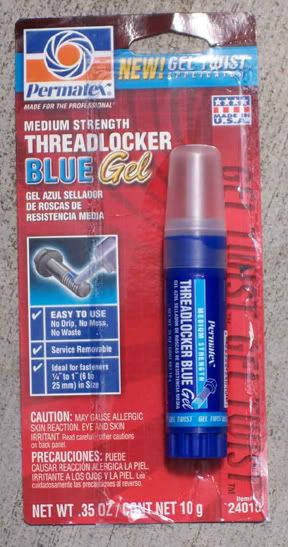
Left to right we have a Dental Pick, a Mirror-on-a-Stick, a Hemostat, and some Uber-Long-Nose-Pliars. I believe it was either rockslide or shorty that enlightened me to the wonderous power that a dental pick has over a sticky o-ring. The pick will peel a tank o-ring off with ease, and its extremely useful for opening the snap ring in a carbine or 98 valve. The Mirror on a stick is great for seeing around, inside, or behind things that might be in the way. I use it equally between paintball, and computer repair. The Hemostat is one of my favorites, you can use it as a small clamp since it locks, or use it to simply grab something. Also works great for holding wires to be soldered together if your fixing an electro. Last, the uber long nose pliars. Nothing beats them for grabbing dropped parts, or retrieving something stuck somewhere. Also spring loaded so theyre easy to use 1-handed. 3: Spray Bottle Carry a small spray bottle with water to your next game. Cleans goggle shots in no time. 4: Teflon Tape (Picture See Below) Use teflon thread sealing tape to seal your hose fittings. I prefer to tear off an inch and a half long piece, fold it in half lengthwise, and then wrap it. Wrap CLOCKWISE around your fitting. And try not to leave any tape hanging off the fitting, as it will tear off, get blown up your air lines into your valve, and fulfill its purpose of sealing something up. Except of course you dont WANT to seal the valve, whoops! 5: Loctite 
Loctite is made for threads as well, but its not intended to seal, just to freeze something in place. Loctite comes in 3 colors (Flavors? Dont try that at home). Purple (Weakest) Blue (Medium) and Red (Its gonna take a nuke to open). Choose your color wisely, or youll end up with a hose with a death-grip on your expansion chamber. Dont put half the bottle on, just enough to lightly cover the threads. And remember to let it cure for 12-24 hours for max strength. Removing loctite is a different story. You can either boil the part, beat on it with something to crack the loctite (sometimes it works), or yell HULK SMASH and get a really big wrench and go to town on it. 5: Basic Multitester Use So you got an electro gun, and you think something is messed up. Hey, why not give it a once-over yourself. You never know, it could be something easy like a broken resistor that you can buy at radio shack for 25 cents. Diagnosing some stuff can be easy, but youre going to need one of these: 
Theres my Amprobe multitester. You can get a good digital tester from radio shack for around $30-50, or a cheap analog one for around $10-20. Now, it depends on what your trying to do, so ill cover the 2 most basic things. First, testing a voltage. Everything in a paintgun will be DC, and you know the voltage pretty easy (Just check the battery). First, find the DC section of your testers dial. On mine this is represented with a V with a solid and dashed line. Not to be confused with a V with a wavy line which means AC current. The rule of thumb when testing a voltage is start high, and work down. Your not going to see a 5000 volt DC source in a paintgun, so lets choose 20. 
Select 20, then apply the probes to what you want to test, red to Positive and black to Negative. If all else fails, read the manual. 
The other common test is checking for Continuity. Continutity simply means testing to see whether something will pass current. Pick one of the levels under Ohms (The little Omega symbol). Mine has an "audible alert" setting whish means if the circuit is good, the meter beeps. Select that if you have it (Or pick a medium number if you dont) and put the probes on the component to be tested. If you get a beep or see the needle move off 0, the component is passing current, and therefore probably not trash. Ill leave it up to you and your imagination to think of what and where to test, but some examples might be checking for contunuity across the wires going to the solenoid valve, checking voltage reaching the solenoid valve, etc. 6: Cheap Pods 
Lost a pod? Go to the gas staton and get some chips! "On the go" doritos that is. They come in this neat case almost the same size as a pod. Sure it doesnt seal very well, but in a pinch... Make sure you wash the chip crumbs out, or you could gum up your gun. 7: Radio Intercept 
Heres a fun, and usually against the rules dirty trick. I have my Uniden Sportcat handheld scanner programmed to scan across all the FRS channels. Ive never used it in a game (yet), but if legal at a scenario or big game, could just make your team more situationally aware. Be sure to use the Lock-Out function to block the ref or official channels. In case your wondering, a Sportcat like mine can usually be had for around $40-60 from ebay. 8: Dirty Barrel Probe Is your barrel gunked up? Got sludge and dirt and paint pieces inside? Fix it! Get a metal coat hanger, cut out the long bottom piece, and bend over the end to clamp either a piece of sponge, or a towel fragment. Chuck that in a drill, and use it to spin-clean your barrel with style. Spray on some water or soap or aluminum cleaner, and it works wonders. |
|
|
|
|
|
|
|
Enos Shenk
Platinum Member
~-o@ Joined: 10 June 2002 Location: A comfy chair Status: Offline Points: 14109 |
Post Options
Thanks(0)
Quote Reply
Posted: 08 March 2004 at 3:24pm |
|
Relocated from New Player
----- So you just got a new shiny Tippmann, and you decided to take it apart. Unfortunately, when you put it back together, it doesnt work. Sucks doesnt it? For that reason, Enos and Reb have made this list of common reassembly mistakes. Inspired by Reb's friend that took his A5 apart and messed it up. ---A-5 Stuff by Enos--- Q: "I screw the tank on, and gas leaks out of the tombstone adapter area really bad" A: Chances are you messed with the valve, or the washer and o-ring fell out of the tombstone slot. Check to see if you forgot to put these parts back in. If you did, make sure you put them in the right order. The washer goes in first, then the o-ring. They should "snap" in, not just sit there loose. Q: "I cant cock the gun, the handle barely moves." A: You put the front bolt in backwards. The raised part with the hole that the link arm fits in points backwards. The o-ring end faces the barrel. Q: "When i go to shoot stuff, it just chops paintballs" A: Chances are you took the halves completely apart (Something you dont need to do), and put the ball detent in backwards. The ball detent should slant up in the direction of the barrel. Q: "Balls just roll out the barrel" A: You forgot the ball detent completely didnt you? Q: "I cock the gun and fire and it barely shoots" A: One of the main causes of this is forgetting the long nail-shaped rod that goes inside the main spring. Remember that the "head" of this pin faces the rear of the gun. Unfortunately if you forgot this part and cocked the gun, it almost certainly ruined your spring. This can also be caused by a backwards ball detent (See above) ---98 Stuff by Reb Cpl--- Ball detent First and foremost, remember your ball detent. It's that little orange thing that sits under the front bolt. It prevents you from double feeding and chopping paint. Forgetting it will force you to clean up your mess and disassemble the marker again to get it right this time. Make sure you put it in the right WAY too. If it's in backwards, the front bolt will jam or not close you'll know if you put it in the wrong way. It's easy to forget this little guy, but it's not something you want to do. Front sight spring. These things are a severe pain if you don't know what you're doing. Make sure it's in properly, as it serves as the latch for the elbow. Without the spring, the elbow has nothing to latch to, and you'll find yourself wondering just how in the heck you keep the hopper from falling off. It's pretty simple once you get the hang of it, you set it in there, then place the front sight over it, on it's pin. That'll hold it in place when you reassemble the receiver halves. Buffer O-ring. If you put your marker back together and theres this large black O-ring left over, it's probably the Buffer O-ring. It's on the 98 Customs, and not the Oldschool 98's. What that does it is keeps the rear bolt from slamming into the endcap. Without it, it'll produce stress on the endcap and bolt. It fits over the drive spring and just sits there. Front bolt Make sure it's in the right way. If you put it in backwards, you wont be able to fully cock the marker. The hole for the cocking rod goes to the rear of the marker. It's drilled into a little square (for the 98c) raised piece or a round raised piece for the M98. Valve Screws These are the two little screws that are on the right side of the marker. They screw into the valve/power tube assembly. When you tighten them, BE CAREFUL. Sometimes you can overtighten them and strip them or their fitting threads, which will result in them falling out later on. That's a bad thing, (duh) because the marker will fail to recock itself and just 'burp' even with a full tank. They are vital, so be careful with them. Safety The safety needs to be in correctly upon reassembling the marker. If it isn't, you may have trouble pulling the trigger, or may have the marker fire on accident. It's pretty simple, there's the words "Push to fire" on one receiver, and "Push Safe" on the other. Set it up so the little red o-ring is on the side marked "Push Safe" This way, when the marker is ready to fire, there's a little red band. Red means shootable. If you look and theres no red band on either side of the marker on the safety bar, the marker should not be able to fire. ---Carbine Series Stuff by Enos--- Q: "What?! I cant get the rear bolt in over the sear!" A: If your skilled you can hold it down with something like a screwdriver, but its difficult. Just loosen the 2 rear gripframe bolts, pull it down enough to get the bolt in, and your set. Q: "I was shooting, and the link arm flew out the top" A: On a carbine series gun, you must have a rear sight on. It holds the link arm in. Q: "The gun wont cock at all" A: You put the front bolt in backwards. The hole for the link arm goes in the back, and the o-ring side faces the barrel. Q: "I got this weird soft rubber thing left over" A: Thats the buffer ring. It slides over the main spring between the end cap and the rear bolt. Q: "When i gas the gun up, it leaks like crazy from the hose where it goes into the gun" A: If you took that hose out of the gun (Which you dont need to do to field-strip), its almost certain the tiny o-ring that goes between the hose fitting and the valve got chewed up. They always do when you remove that fitting. Find a replacement. |
|
|
|
|
|
|
|
beltismad,yo
Member
Guested - Flaming Joined: 15 February 2004 Location: United States Status: Offline Points: 1211 |
Post Options
Thanks(0)
Quote Reply
Posted: 10 March 2004 at 12:20am |
|
I figure this might help y'all a little bit: I have made almost all of the reassembly misteaks possible on an SL68II. Being a pump, and a Tippmann, it is fairly simple. If you've ever taken one apart, there are what? About 6 or 7 parts that you can easily take out. (Front bolt, hammer, valve assembly, end cap, bolt spring, and the valve spring.) The rest is held in place by pins, and only needs to be taken out when you are replacing or modifying it. To disassemble a SL68II, first and foremost; DEGASS IT AND TAKE THE TANK OFF. If you don't, you'll have a not-so-pleasent suprise when you fianlly take it apart. Losen the pinch screw underneeth the barrel, and slide the barrel and pump arm out. The front bolt will come with the pump arm, so be careful. (First time I disassembled my SL68II, the bolt fell off and slid across the room.. not good) Try not to drop the bolt, if you do, it may not end well. The Bolt spring should come out next. Next, you need to get the hammer out. I find it easiest to squeeze the trigger, and knock the front of the reciever ont something. Weather it be your palm or the desk, just be careful not to break it. It should slide right out once you loosen it. If so so desire, you can take the valve out. All you need to do is take your allen key, and slide it into that hole on the side of the end cap. Then loosen it, and take it out. The end cap is uber long, so it will take quite a while to fully unscrew it. Next, pull out that little valve spring that is in there. I find it easy to knock the back of the reciever against something to loosen the valve up, so it will fall out. Give it 5 or 6 good wacks against your palm, it should come out. After you clean it, and oil it, it comes to reassembly. This is the hard part. I usally put the valve and end cap in first, when I'm reassembling my SL68II. Slide the valve back in, along with that spring that goes behind it. Screw the end cap back in, until it is hand tight, then finish it off with the allen key. Rember, make sure it is tight, beacuse when you gas it up, and fire it, there is about 800 psi on this part.. you want to make sure it is in there good. But, Do not over tighten it. Now, you can do this next step one of two ways. You can either, take the bolt and hammer (with the spring in the middle) and try to push them togeather, until the sear lock into place. (hard to do, and dangerous) Or slide the parts in one by one. I usally put the parts in one by one. Take the hammer and slide it in. Make sure that the "hook" end is facing twords the FRONT of the reciever. (look on the bolt, see that little square section cut out? the hook needs to latch onto that..) The smooth side of the sear goes twords the REAR of the reciever (twords the valve). I find it easy to squeze the trigger, and push the hammer in. It should slide right in. Next goes the bolt spring. Just drop it in there. This next step may be a little hard for those of you with a lower-than-average I.Q. but, follow directions carefully, and you wont have any problems. Take the front bolt and look at the bottom of it. There should be one hole, on the bottom, twords the front of the bolt. (The front side of the bolt has an O-ring on it) The linkage arm for the pump handle fits into that hole. Slide the linkage arm into that little hole. Next, slide the barrel back into the pump handle. After you do that, slide the whole assembly back into the front of the reciever. Push the barrel all the way back, then tighten that little pinch screw.
Your SL68II should now be fully assembled. |
|
|
I'm giving up flaming and spamming, in my efforts to improve the forum. (Don't laugh)
Belt Still Pwns Joo. |
|
|
|
|
brutl_force
Gold Member 

One Truck’n Machine! Joined: 18 August 2002 Location: United States Status: Offline Points: 1887 |
Post Options
Thanks(0)
Quote Reply
Posted: 14 March 2004 at 8:25pm |
|
I see a lot of people asking how to remove damaged body screws, so:
I have found that special left handed bits, easy-outs, damaged screw removers, and liquid wrench are actually the long, expensive way to do it. The process of removing a damaged body screw(rounded head) is reletively simple. 1. remove a body screw that you CAN remove. 2. Go to your Dad's tool box and get a bit that fits down the shaft that the screw goes in. (A bit with a slightly smaller diameter than that of the screw) Or get a cheap set from your hardware store of choice.It should not be a lot smaller, just enough to easily travel through the hole. 3. Drill off the head of the bad screw. Be sure to drill strait down. The head will come off and stay on the bit. It will probably take a pliers to get the bolt head off the bit, but not an issue. 4. Remove all other screws and take the gun apart. 5. Go to the screw that you drilled, and simply use your fingers or a pliers and easily screw out the remaining screw shaft. 6. When you are ready to put the gun back togeather, put in a new screw, and buy a set of new allen wrenches (preferably stainless steel) due to the fact that the Tippmann wrenches are soft steel. Thus they round, and in turn round out the bolts. Works great, do it all the time. Brutl |
|
|
Inclementia Vigor (Translated from latin to brutal force). And yes, I spell "brutl" wrong on purpose.
|
|
|
|
|
ANARCHY_SCOUT
Platinum Member

strike 1 1/24 rudeness to newer members Joined: 07 August 2005 Location: United States Status: Offline Points: 4439 |
Post Options
Thanks(0)
Quote Reply
Posted: 21 September 2005 at 8:48pm |
|
98 custom double trigger So you want a double trigger and you want to save money? heres the ghetto cheap way to do it. 1. take out the single trigger. 2. Sand down the little bump at the end of it. 3.drill a small hole in the middle of the bottom. (carefull not to drill to far in because it might crack the trigger.) 4. put a allen wrench in the hole that fits snuggly. 5.make sure you put like super glue or Jb weld glue in the hole. 6. cut off the angeled part of the allen wrench. 7. wait and let the glue dry. 8.put it in and try it. 9. make shure to make some kind of trigger gaurd. I am not responsible for any problems you have.
|
|
|
Gamertag: Kataklysm999

|
|
|
|
|
Bruce A. Frank
Platinum Member

KRL Reincarnated? Joined: 27 March 2004 Location: United States Status: Offline Points: 3063 |
Post Options
Thanks(0)
Quote Reply
Posted: 30 January 2006 at 4:14pm |
|
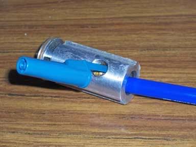
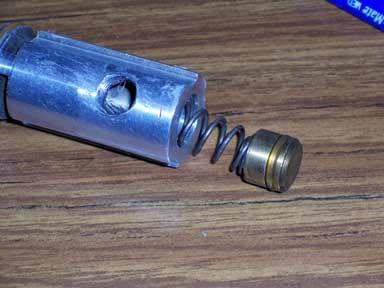
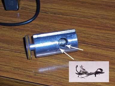
Disassembling Your Power Valve I am sure this sequence, on taking apart the power valve, has been posted before. I have posted the sequence with just a verbal explanation. But, I have just acquired a digital camera and can clarify some of the steps. After removing the power valve from your marker the disassembly is started by depressing the end plug. This is the brass plug in the opposite end from the pin. Anything can be used as a tool suitable to the job. In my case I used a blue plastic ball point pen. Using the blunt end of the pen I pushed the plug down the barrel of the valve. When the plug reach the opening into which the braided line fits, I used the pen cap to block the plug and hold the spring compressed.
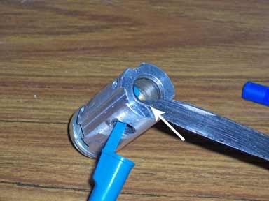
Next the clip ring or circle ring must be removed. The ring has a small tip that you can gently pry out of the groove using a tool like a dental pick or, in this case, a knife blade. Take care if you use the knife. If you slip you are stabbed or possibly badly cut. Any tool with a point of some kind will work.
You can see here the tip of the blade has pried the tip of the clip away from the groove and has been slipped under the tip to prevent it from snapping back into its slot.
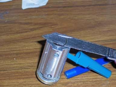
You can then just rotate the valve body causing the ring clip to spiral over the blade and out of the barrel of the valve.
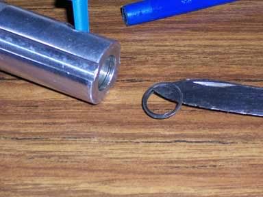
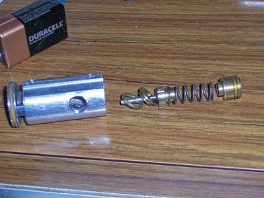
And it is out! Next, reinsert the blunt end of the pen to depress the plug and remove the pen cap. Slowly release the pressure on the pen to allow the valve's internal spring to push the plug back to the end of the valve body.
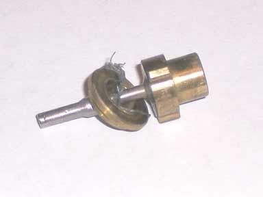
You may have to tap the valve body on the table top to get the plug to pop out. This particular power valve is an original one with all standard parts. The valve that comes with the Low Pressure Kit differers slightly, but not in any way that changes the disassembly procedure. The low pressure valve has a spring with smaller diameter wire with more coils per inch. (The gold colored "O" ring you see on the plug can sometimes crack, but rarely, and be the source of a gas leak) The next step is to remove the pin valve, it's seat and the "O" ring seal. You can push the pin valve into the body of the power valve. Then shake, or let it fall, out of the open end of the valve body.
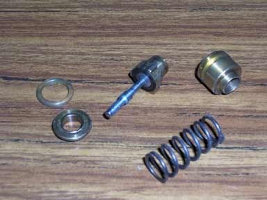
Here you can see all the internal parts. Right to left: The plug with its "O" ring seal; next the spring; then the pin valve; and the pin valve seat (a brass "washer" with a small ridge on its inner edge that embeds into the inner rubber face of the pin valve's head to create the seal and stop gas flow);and last is the "O" ring seal that seals the underside of the seat washer to the inside of the power valve.
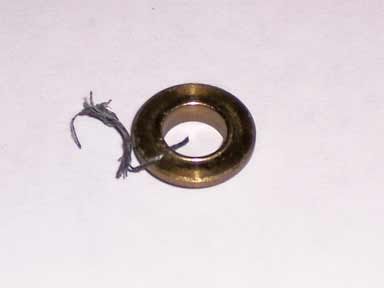
When your valve leaks gas, that comes out of the barrel, these mating surfaces, the rubber face and the brass washer with its embedding ridge, are not seated against each other properly. Usually it is just a piece of trash that may be flushed from between the surfaces with a little oil squirted into the ASA followed by several shots (gas pressure shots, no paint and no barrel to prevent oil from getting into the barrel). It that does not clear the trash and stop the leak, you then move to this disassembly task as explained so far. After complete disassembly you will have these parts on the table top.
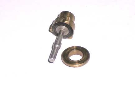
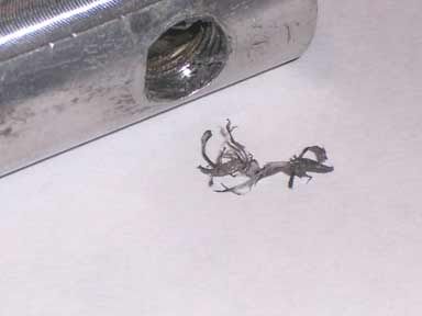
EDIT June 3,2007 There is a little trick here that may reduce the likelihood of a leak when reassembling the valve. The pin can be unscrew from the brass head (take care not to scratch the pin...I use a small piece of leather between the jaws of my pliers to protect the pin shaft) and the black rubber (actually a very firm plastic) sealing washer then can be removed. That washer will have a groove imbedded into the surface where it has been sealing against the brass ridge. When you reassemble, every once in a while the seal between the brass seat and the washer doesn't align and a leak can happen. Over time it usually reseats and the leak goes away. But, take the washer and flip it over. The back side is as smooth as brand new. Re-assemble the pin valve and re-install it with that "new" side out and 99 out or 100 times the re-assembled valve with work perfectly with no leak at all. The potential for a leak in these mating surfaces is why many pro shops wilL not rebuild valves. But you can do it! =============== Oiling and letting a reassembled valve sit for a while may allow the parts to conform again and the valve may seal. =========== There have been discussions as whether to use Loc Tite or Teflon ribbon to seal the threads when the braid is screwed into the power valve. When I got this valve apart I noticed something hanging from the threads inside the valve body. It was a shredded bit of Teflon ribbon. The picture below shows the stuff with the arrows. The inserted picture shows what it looked like after I pulled it out with a pair of tweezers.
Strands of this, even though it is soft, can get between the sealing surfaces of the pin valve and cause a leak.
From this find of Teflon in the valve I'd recommend that those with little experience using Teflon ribbon should stick with Blue Loc Tite. Teflon certainly can be used, but a lot of care must be taken to not wrap it too close to the end of the fitting. Use it back from the tip of the fitting just so it is in the threads as they engage the hole. Even then, when fittings are removed care should be taken to brush or tweeze the remnants of the ribbon from the threads. If not removed, when the fitting is placed back into the hole it will push those shreds into the valve. If you have any questions, if there needs to be clarification, just ask. ====================== Thought I'd come back and add a little about Blue "Loc Tite." The stuff that works well is the gel. It sets up ("drys") quickly, seals well, and can be adjust after it is "hardened" and it still doesn't leak. You can immediately, after putting thing together with it, pressurize the system. It also is a medium locking material so that the parts can be taken apart with standard tools. (I use the name Loc Tite interchamgeably with Permatex...the products are virtually the same...certainly the colors are.)
Edited by Bruce A. Frank - 16 August 2007 at 3:06pm |
|
|
|
|
|
|
hapet02
Member

Joined: 14 February 2006 Status: Offline Points: 4 |
Post Options
Thanks(0)
Quote Reply
Posted: 22 March 2006 at 9:50pm |
|
nice work guys
|
|
|
|
|
bassist11
Member

Joined: 23 June 2006 Location: United States Status: Offline Points: 392 |
Post Options
Thanks(0)
Quote Reply
Posted: 11 July 2006 at 10:58pm |
|
very nice stuff. extremely helpful. thanks
|
|

|
|
|
|
|
an94
Member

Joined: 24 June 2006 Location: United States Status: Offline Points: 514 |
Post Options
Thanks(0)
Quote Reply
Posted: 30 September 2006 at 9:59pm |
|
how about some imfo for Ebolts?
|
|
|
1 paintball gun package=$150
1 case of paint=$50 air & entry fee=$15 lighting up newbies all day long= Priceless |
|
|
|
|
detroit sultans
Member

Joined: 17 December 2007 Location: United States Status: Offline Points: 2 |
Post Options
Thanks(0)
Quote Reply
Posted: 17 December 2007 at 10:37am |
|
i have a tippman 98 pro with act and e grip for some reason i fire my gun and it wont stop fireing until i grab the firing pin
|
|
|
|
|
Post Reply
|
Page 12> |
 Tweet
Tweet
|
| Forum Jump | Forum Permissions You cannot post new topics in this forum You cannot reply to topics in this forum You cannot delete your posts in this forum You cannot edit your posts in this forum You cannot create polls in this forum You cannot vote in polls in this forum |


 Topic Options